SoundGrid System Design Guidelines
Learn about various aspects and find guidelines for building your SoundGrid system. There are several factors that need to be taken into consideration when designing and building a SoundGrid system, here we break them down and discuss each component of the system in depth, and provide an overview of the system as a whole.
The information below is relevant for all SoundGrid applications, but for the sake of convenience, we focus here on the eMotion LV1 mixer as the prime use-case example.
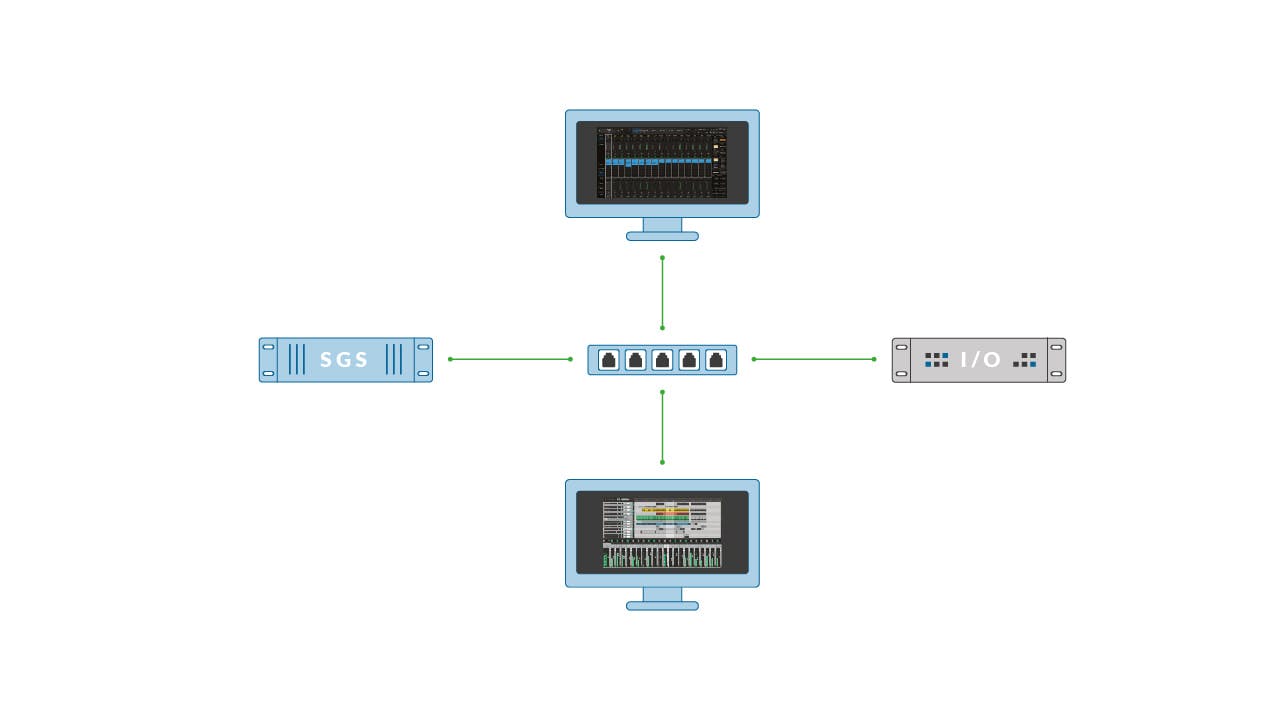
A complete SoundGrid system is comprised of the following components:
- A Host computer – a Windows/Mac machine running a SoundGrid application (eMotion LV1/SuperRack/SoundGrid Studio) and Waves plugins.
- At least one SoundGrid Interface I/O device (Stage box, expansion card, bridge/converters)
- At least one SoundGrid Server, this is where the audio processing takes place.
- Additional Mac/Windows computer(s) for playback/recording using the SoundGrid ASIO/Core Audio DAW driver.
- A touch screen and/or control surface(s) - FIT controller, MyRemote mobile applications, Mackie controller or MIDI controller, DiGiCo & Lawo remote integration.
- Network switch/s
- Network cables
The host computer is a Windows or Mac computer that runs the SoundGrid application (eMotion LV1/SuperRack/QRec/SoundGrid Studio). It is responsible for hosting the user interface (GUI), controlling and configuring the audio connections, plugin instantiations and parameters of the mixer.
Waves officially supports any computer that meets the minimal specifications in the System Requirements page. Note that system requirements are usually updated in every major version update.
Waves highly recommends using these computers, customized specifically to run Waves SoundGrid applications:
- Waves Axis Scope – recommended for all LV1 configurations.
- Waves Axis Proton – recommended only for 16-ch. and 32-ch. LV1 configurations
- Waves Proton Duo - recommended only for 16-ch. and 32-ch. LV1 configurations at 44.1/48kHz
- Waves Axis One – recommended for all LV1 configurations
Waves also recommends the following systems that were officially tested and qualified:
When building or purchasing a computer dedicated to hosting the Waves eMotion LV1 live mixer, please follow the specifications and guidelines presented in our ‘ How to Build or Purchase a Computer for eMotion LV1’ article.
eMotion LV1 supports up to 4 touch displays (subject to the host computer’s capabilities and specifications). In most setups, using 2 touch displays or 1 touch display and a FIT controller will cover your needs to conveniently control the mixer.
Windows supports multi touch (10-touch points) natively, whereas macOS does not offer native touch support.
To connect your Touch display please use an HDMI/DisplayPort cable and an additional USB cable for touch.
To calibrate your touch screen on a Windows machine please refer to the How to Calibrate Touch Screens on Windows article.
Ideally the host computer should have a network interface card (NIC) with an RJ45 port. Some computers do not have an RJ45 port, and in that case, an adapter can be used. In the upcoming sections, we will discuss the additional role that a Mac/Windows computer can have in a SoundGrid system and explain the importance of selecting the correct adapter for your specific scenario.
Some features of SoundGrid applications (such as MyRemote mobile applications or TRACT Sound System Calibration plugin) may require an additional, separate network connection on the host computer. If there is no 2nd port, an adapter can be used in this case too. As a rule of thumb, you should not mix between the audio network (SoundGrid) and other network protocols.
Please refer to the Windows PC optimization guidelines article for a list of recommended settings for optimal performance with your Windows PC and SoundGrid.
Waves and its partners offer a wide catalog of SoundGrid compatible audio interfaces to choose from. Aside from SoundGrid stage boxes, which provide a complete A/D & D/A path, almost any type of known digital audio protocol can be converted to/from SoundGrid, allowing easy SoundGrid integration into an existing environment, using MADI, console expansion cards, AES 3, AVB, Dante and more.
Visit the SoundGrid Interfaces compatibility chart to explore the full range of SoundGrid I/Os available on the market.
When designing a SoundGrid system, clocking should be taken into consideration. All SoundGrid I/Os have an internal clock and can also receive a clock from an external source via Word Clock, Digital stream, or via SoundGrid’s proprietary sync protocol, SoE (Sync-over-Ethernet).
SoE is the proprietary clock distribution protocol of SoundGrid. It distributes clock frames across the SoundGrid network, on the same links used to transfer audio. In a SoundGrid system that has more than one device, you will have to decide which I/O is the clock master, and all the other I/Os on the network will be automatically Synced Over Ethernet to it (SoE). Setting up an I/O device as a clock master is done in the SoundGrid inventory page, in the device’s menu. There are setups where there is no one correct choice. However, in certain setups, you will need to comply with a specific configuration.
So which SoundGrid I/O should I set as my SoE clock master?
The SoundGrid clock master I/O would ideally be a device that sits on the same network switch as the main SoundGrid server.
Placing a SoundGrid Server on a different switch as the SoE clock master I/O is fine, but keep switch hops to the minimum possible.
If there are multiple SoundGrid I/Os connected to the same network switch as the server, the natural choice for clock master would be the main stage box, or a device that has dual power supply, such as the DSPro StageGrid 4000.
If you are looking to synchronize a SoundGrid system to an external clock source coming from a digital mixing console or another audio network protocol, you would usually choose the I/O device that bridges the 2 systems, as the SoundGrid System’s clock master. In that case, go to the I/O’s control panel in the SoundGrid application and set its clock source to 'Digital' or ‘Word clock’, depending on the specific use case. This I/O will distribute the clock signal via the network to the rest of the SoundGrid devices using the SoE protocol.
You can also go in the opposite direction and have the external system sync to SoundGrid. In that case, the I/O device bridging both systems does not necessarily have to be selected as the SoundGrid clock master. If it is selected as clock master, its clock source should be set to 'Internal'. You can also set a different SoundGrid I/O from your setup as the clock master, while the I/O bridging the 2 systems is synced to that I/O via SoE. In that case, it is important to make sure that the external system’s clock source is set to sync to SoundGrid.
Important notes:
- Failure of the SoE clock master will cause a 1~ second mute until SoundGrid finds a different master, if available.
- Failure of the link between the SoE clock master and the SoundGrid Server will also cause a mute.
- For example, if the server is located at the operator’s FOH position while the SoE clock master is located on stage, and the link between FOH and stage switches goes down, there will be a mute. If both devices (SoE clock master & main server) are connected to the stage switch, audio should keep flowing even if the link between the two switches fails, except for sources/destinations located in the FOH position
- When using DiGiGrid Q/M/D desktop interfaces in a setup that consists of more than one SoundGrid I/O, make sure that the DiGiGrid desktop interface is only set to sync from SoE and not its own Internal clock or as the system's clock master.
The SoundGrid Server is the CORE of a SoundGrid system. It is a computer running a customized Linux operating system with the sole purpose of processing audio. It handles plugin processing and serves as the mixing and summing engine of the system. The server is an integral part of the SoundGrid system. Without it, no audio will flow through the mixer.
There are several models to choose from. SoundGrid servers such as the Titan Server or the SoundGrid Extreme Server are 2U full rack size, while the Compact ‘C’ series are 2U half-rack size.
When purchasing a SoundGrid server, it is important to refer to the Compare Servers page for plugin processing benchmarks.
It is also important to make sure that the server model you choose, whether it is the Titan, Extreme, One or Proton, meets your technical requirements in terms of sample rate, eMotion LV1 license type (16, 32 or 64 channels) and the amount (and type) of plugins that you intend to use.An additional server can be used to act as our backup server. If the main server fails, the second server will kick in and continue to process the audio. In this situation, a momentary mute in the system will take place, until the system has re-synchronized itself.
When setting up server redundancy, it is recommended to use two identical server models so that in case of a failure, the redundant server will be at least as strong as the main server so it can properly handle the CPU load.
When you have two servers connected and assigned as your main and redundant, you can perform a quick redundancy test to ensure that the system is working as expected. To do so, right click on the server slot menu and press on ‘Test Redundancy’. This will perform automatic server switching. You can also test the redundancy by physically disconnecting the main server’s Ethernet cable and witnessing the backup server taking the roll of processing the audio.
Please note that a short mute will occur while the server switchover takes place, as the system re-synchronizes itself.
One can utilize up to 4 servers to add more processing power, by designating servers to selected plugin racks.
In the eMotion LV1 Mixer, groups A acts as the audio engine. The main server assigned to group A must be continuously assigned for audio to pass.
To increase plugin processing capacity, one can assign selected plugin racks to additional servers that are assigned to groups B/C/D. When doing so, audio is sent from group A's main server to the additional auxiliary server(s) and returns to main server in group A, post-processing. This routing adds some latency to the rack.
Should the auxiliary server fail, audio will not be completely lost. Rather, rack processing will be bypassed, and the audio will remain unprocessed until the disconnected server is back online again.
The rack's latency value will remain the same in the path to the mixing buss, even though it is bypassed.
Ideally, any additional servers should be physically placed as close as possible to the main server. Good practice is to place it on the same network switch together with the main server that’s assigned to group A.
While in LV1 server groups B/C/D receive and send audio to group A's server, In SuperRack SoundGrid, as no summing is taking place, audio is fed to the SoundGrid server directly from a SoundGrid I/O device. This means that racks assigned to a server that has failed will not pass audio.
Standard Mac/Windows computers can be used to send/receive audio from the network, using the SoundGrid DAW Driver. The host computer can perform this task in parallel to hosting the SoundGrid application, however, it is highly recommended to use a dedicated computer for the purpose of recording or playback.
Each computer can stream up to 128 channels to/from the network. The higher the channel count, the more resources required, so it is important to ‘spec’ a powerful enough computer to handle the task at hand.
Multiple computers can be used simultaneously, and it is advised to dedicate each machine to a specific task.
For example, one setup may have 4 computers:- An Axis Scope hosting eMotion LV1
- A Windows computer for playback
- A Mac for recording
- A 2nd Mac for recording backup
Please see the SoundGrid Driver system requirements page for more information.
As stated in the Host Computer chapter above, the Mac/Windows computer that you use with the SoundGrid DAW driver should have an RJ45 port available. If that is not the case, then an adapter should be used.
Mac users: For best performance of audio transport from the SoundGrid Core Audio Driver to the SoundGrid network, Apple computers should use one of the following adapters:
- Sonnet Solo 10GB Thunderbolt 3-to-Ethernet Adapter (Type C connector)
- OWC Thunderbolt 3 10GB Ethernet Adapter (Type C connector)
- Apple Thunderbolt 2 to 1GB Ethernet Adapter (MDP connector)
Recording and playing back over 32 channels using your local Apple ethernet port is not recommended and may cause random audio drops. This is to ensure optimal prioritization of SoundGrid audio packets. Generally, on-board LAN ports and USB-C to Ethernet adapters may work well when recording/playing back low channel counts (below 32), or, when the computer is used as a SoundGrid application host only.
Windows Users: For best performance of audio transport from the SoundGrid ASIO Driver to the SoundGrid network, Windows computers featuring USB-C connectivity should use a Gigabit Ethernet adapter with an Asix AX88179A chipset. We've specifically tested the following adapter: Pluggable USB Type-C Gigabit Ethernet Adapter USBC-E1000.
SoundGrid is based on Gigabit Ethernet (1000Base-T), so any standard 1Gbps network switch might work fine, however, it is recommended to use switches that were tested and qualified by Waves.
Please visit the Network Switches for SoundGrid systems article for a list of supported switches.
It is important to remember that SoundGrid is a ‘private’ network: to ensure a clean network stream, the SoundGrid network must be isolated from other networks. Using non-SoundGrid devices on the same network switch might result in audio drops and other unexpected behaviors. Therefore, do not mix protocols on the same switch. A common mistake is connecting the Internet to the SoundGrid network.
If using several protocols on a single switch cannot be avoided, it is recommended to implement VLAN, which enables you to logically divide one physical switch into smaller networks that do not “see” each other. This will require a managed switch. Some of the switches that were tested for SoundGrid are managed, which allows VLAN to be configured via the switch’s management interface. To learn more about using SoundGrid in a VLAN please refer to the How to use SoundGrid network in a VLAN article on Waves’ website.
Some switches offer fiber optic connectivity. This is a great solution for those who use multiple switch configurations, where a distance of more than 100m / 328ft is required between switches. Note that using fiber cables requires an SFP Module to be inserted into the relevant port on the switch - those are usually purchased separately. Refer to the Network switches page to learn which models offer fiber optic support.
Make sure to connect to your network switch with a high-quality Ethernet cable. Visit the Ethernet cables for SoundGrid systems page for additional info.
Additional features and notes:
- DigiGrid IOX/IOC/IOS/IOS-XL/MGR interfaces are equipped with a 4-port network switch. Daisy chaining additional SoundGrid I/Os through the DiGiGrid switch is not recommended.
- Link Aggregation Group (LAG) is a feature that offers cable link redundancy between two network switches by aggregating 2 links or more into one logical connection and spreading the work between them. If one cable fails, the data stream will fall back to the remaining members of the LAG group. Waves officially supports LAG with selected network switches, as listed in the Network Switches for SoundGrid systems article. Note that the LAG feature was only tested and qualified where both ends of the cables are using the same network switch model.
- Power Over Ethernet (PoE) - SoundGrid I/Os such as DiGiGrid Q,D or M can be powered over Ethernet (PoE) - To find out if a switch supports PoE, please refer to the switch documentation.
- Energy-Efficient Ethernet (EEE) or Green Ethernet – This feature should NOT be used with the SoundGrid network as it can cause unexpected behaviors when the switch reduces power in energy-efficient mode.
Waves SoundGrid servers and I/O’s have EEE disabled by default, meaning that in most cases, EEE will not function. However, if more than one unmanaged network switch or when a computer with EEE enabled is connected to the SoundGrid network, the sync of the SoundGrid system may be affected. We recommend verifying that EEE is disabled on your host computer by following the steps in this article.
In a multi-switch system, such as an eMotion LV1 system that includes two consoles, one at Front-of-House and one at the monitors position, we recommend using managed network switches, where this feature can be turned off or is off by default. - The use of Fiber Media Converters is not officially supported by Waves. When long distances are required, please use a switch that offers fiber connectivity.
There are several types of network cables available on the market. Waves officially recommends using Cat5e, Cat6 & Cat6a cables whenever possible.
Other cable categories such as Cat7 or Cat8 are less recommended. SoundGrid supports Gigabit Ethernet, while Cat7/8 data rate is much higher. When connecting such cables to lower category feed-through connectors (Ethernet Couplers), the risk of signal degradation grows due to impedance mismatches along the cable’s path, from end to end. This phenomenon can potentially cause unwanted behaviors such as audio drops/data loss.
Additionally, Cat7 is not officially ratified by the IEEE association. There could be variations and inconsistencies between different cables manufacturers across the global market, while Cat5e and Cat6/A are widely adopted.
Unshielded cables such as UTP are not officially supported, as those are more susceptible to electromagnetic interference (EMI) and crosstalk, while shielded cables are less susceptible to EMI & Crosstalk. For this reason, it is recommended to use S/FTP or STP-type cables, especially for long cable runs.
Per the Ethernet Cables page, the supported cable length between each device in the network to its network switch is:
- Server to switch - up to 10m/32.8ft
- Host computer and/or DAW driver computer to switch - up to 100m/328ft
- Network switch to network switch - up to 100m/328ft (for greater lengths use fiber optic cables)
- I/O to switch - Up to 100m/328ft
- *DiGiGrid IOX/IOC/MGR/IOS/IOS-XL/D/Q/M to switch - up to 70m/229ft.
When using cables with etherCON connectors, please avoid using Cat6 connector type. Instead, use a Cat5e or Cat6a etherCON connector type. The shell design of Cat6 is different, so these cables will only intermate with specific etherCON Cat6 Chassis connectors which are not widely used. When not using etherCON, you may use Cat6 cables with RJ45 termination.
For more information visit the Ethernet Cables for SoundGrid Systems page.
Bend radius is the minimum extent a cable can be bent without suffering damage. The appropriate bend radius for each cable can be calculated according to the cable’s diameter. When cables are bent beyond this predetermined minimum bend radius, it can cause data loss. As a rule of thumb, it is recommended to avoid sharp cable bends.
When connecting switches using fiber optic cables, please make sure to follow the following cable requirements:
- Make sure that the optical connector that you use is a Duplex LC Connector interface
- Make sure that the cable supports data links of up to 550m in 50/125μm Multi Mode Fiber
- Make sure that the cable supports data links of up to 275m in 62.5/125μm Multi Mode Fiber
Please note that SFP modules are needed to connect fiber optic cables to the fiber ports on your switch. Some of the switches Waves has qualified for were tested with specific SFP modules. Those are mentioned in the Network Switches for SoundGrid Systems webpage and are purchased separately.
A chassis connector joins two ethernet cables. It is usually installed in a rack panel mount, providing easy access to devices with fixed wiring inside. Such connectors are ‘feed-through’ and are not considered ‘hops’ - as no switching is taking place.
When adding a chassis connector or ethernet coupler between two endpoints, you are potentially decreasing the data quality of the given line, making it more susceptible to signal degradation. Therefore, it is important to verify that the category of your ethernet cables matches the category of the chassis connector or ethernet coupler that you intend to use.
For example, it is less recommended to use a Cat5e chassis connector between a Cat6 cable and a Cat5e jumper cable. You should be using Cat6/Cat6A into a Cat6A coupler connected to a Cat6/Cat6A jumper cable that goes straight to the switch, inside the rack.
This is to maintain the same cable category from one end point to another.For the best results, use high-quality shielded connectors.
For Cat6/A cable runs, it is recommended to use the Neutrik Cat6a NE8FDX-P6.
For Cat5e cable runs, it is recommended to use the Neutrik Cat5e NE8FDP.
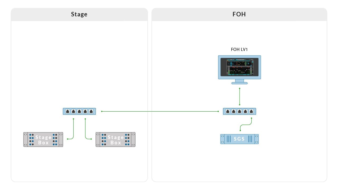
SoundGrid setups that run SuperRack, SoundGrid Studio or QRec, will usually include a singular switch, while eMotion LV1 is a full-blown live sound system, that can potentially include many I/O devices, servers, hosts, and switches. This is where proper system design comes into play.
When designing your SoundGrid network, it is important to stick to a star configuration and minimize the number of switch hops as much as possible.
Since each network interface in the network is limited to a bandwidth of 1Gbps, Star topology helps SoundGrid to handle heavy traffic loads on the network, so that each link will only carry the data that’s relevant to and from the specific end point device to the switch.
In a Star topology, all devices in the network are connected to a central switch that receives all incoming data and then forwards the data to the appropriate destinations.
Although some SoundGrid I/Os have built-in switches (such as DiGiGrid interfaces – IOX, IOS, IOC, MGR), it is not recommended to daisy-chain devices. For example, if you have four IOX devices in a stage rack, then run four separate cables—one from each unit to the network switch—as opposed to daisy-chaining the devices.
Note that Star topology is recommended in the context of a singular local switch – when using multiple switches, for example, one at Front of house and one on Stage, the link between those switches will potentially carry data to and from multiple devices. It is recommended to make sure that the link which connects the switches is not overloaded.
An easy way to calculate this is to add up the maximum channel count that each I/O can transfer and receive to and from the network, on a single link.
The general rule of thumb is that a 1Gbps link can run up to 512 channels at 44.1/48kHz, and 256 at 88.2/96kHz.
For example, when using 2 DSPro 4000 units on stage (each with 40 available inputs and 28 outputs, including analog, AES and headphone outs) and the SoundGrid Server is located at the FOH position, you will potentially run 80 inputs and 56 outputs on that single link, connecting the 2 switches. At 48Khz, this is about ~%15 of the available bandwidth, while at 96Khz it is about ~31%. This calculation shows that in both situations you are well below the point of overload.
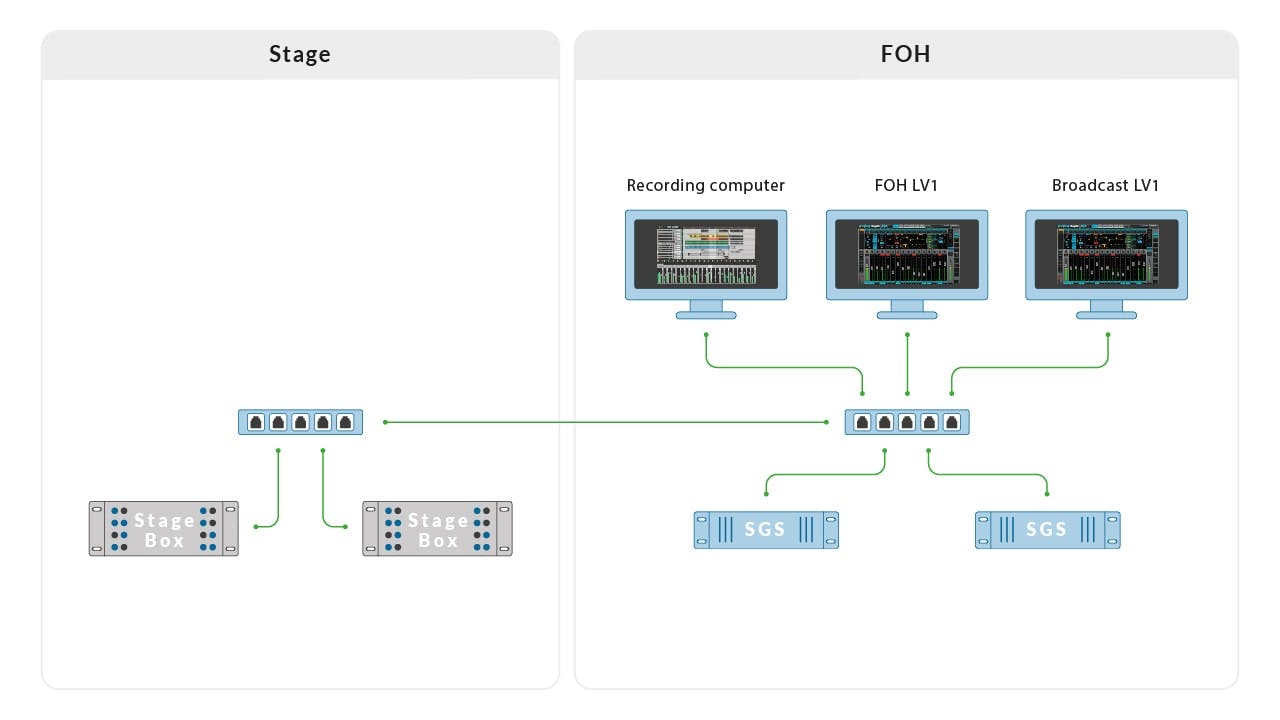
Each patch creates a discrete connection between the source and destination. When patching a device to more than one destination, for example, patching inputs to a recording computer or using I/O Sharing to send the same set of inputs to an additional SoundGrid server and host, you would need to multiply the channel count by the number of destinations.
For example, if you send a single mono source to 3 different destinations, the device will output 3 channels to the network. If you send 32 channels to 3 destinations, the device will output 96 channels to the network.
Going back to our previous example, let us add an additional host computer running eMotion LV1 (Utilizing I/O Sharing), a SoundGrid server and a recording computer running the SoundGrid DAW Driver to record the stage box inputs, all running on the same FOH switch. In this case, you will potentially be transferring 80x3 (240) inputs from the stage boxes to eMotion LV #1, eMotion LV1 #2, and to the recording computer. At 48Khz, this is about 47% of the available bandwidth, while at 96Khz it is about 94%. This calculation shows that in 48kHz you are below the maximum available bandwidth, while at 96kHz you are almost at the point of failure. To clarify, in this example you did not take the output count into consideration, since only inputs can be split to more than one destination. Outputs of an I/O device can be used by more than one host, but each output is exclusive to its patched owner. Simply put, this means the output count stays the same (56).
Every ‘switch hop’ in the signal path adds latency, due to buffering in the switch, and while Waves supports up to four ‘hops’ between point-to-point, it is highly recommended to minimize ‘switch hops’ whenever possible. This is especially important when designing ‘Super Systems’ that consist of multiple LV1 and SuperRack hosts in several locations on-site. Such a system can sometimes include 5-6 network switches, according to the requirements of the specific production facility. This is ok, as long as the audio paths between 2 end points do not exceed the 4-switch hop rule of thumb.
A common question that comes up when designing a SoundGrid system is - where should I place the SoundGrid server?
The answer to this question will vary according to the size of the network. Since the server sync relies on the SoundGrid SoE clock master of the system, it is advised to keep the server and the clock master as close as possible, preferably connected to the same switch. However, in smaller setups (for example: 2 switches, stage, and FOH), server placement does not play a crucial role, and is dependent on the operator's preference.
In large super systems, it is wise to centralize SoundGrid servers and main I/O devices as much as possible, so that all I/O devices have the shortest path possible to the server and the clock master, given that both the I/O clock master and the server are connected to the same ‘main switch’. This will, of course, vary significantly per use case and conditions, but as long as the 4-hop limit is not exceeded, it should be fine.
To ensure that your system operates under optimal conditions and to extend the longevity of your devices, please follow these racking guidelines:
Ventilation and Physical Placement
Allow Adequate Ventilation:
- For DigiGrid’s IOS/IOS-XL/IOX/IOC units, it is recommended to allow at least a 1U gap above the unit to ensure sufficient ventilation.
- Provide sufficient space for ventilation above SoundGrid Servers and Axis Scope/One computers.
Maintain Clean Ventilation Grills:
- Ensure that all your SoundGrid devices' ventilation grills are free from dust. If dust accumulates, unscrew the grill panel and clean the dust filters.
Power and Grounding
- Use Mutual Power Strips.
- Connect all devices in a rack to a shared power strip.
Proper Grounding:
- Ensure the rack and its devices are well earthed, and that their power sockets have good contact with the ground.
- If you are using a Panel Connector Chassis to accommodate powerCON connectors, ensure all connectors are properly grounded.
Power On/Off Procedures
- For guidance on the proper manner to power on and off the SoundGrid system, please refer to the Best Practices for Powering SoundGrid Setups On and Off article.
Network Accessibility and Cabling
Design for Network Switch Accessibility:
- For troubleshooting purposes, design your racks to allow easy access to the network switch.
Extend Network Switch Ports:
- For convenient access to rack devices or to connect two racks together, it's common practice to extend network switch ports to a rack panel mount. When doing so, use etherCON connectors that match the category of your cables.
Ethernet Cables and Connectors
Use High-Quality Ethernet Cables:
- Ensure all Ethernet cables, especially CAT6A, meet industry standards for impedance and resistive balance.
- Avoid cables with resistances above the 4 Ohm threshold to prevent performance degradation and data errors.
How to Ensure Compliance:
- Use proven, reliable cable brands.
- Use a cable tester to measure the DC resistance of your cables.
- Refer to the cable's datasheet to confirm compliance.
Ensure Consistent Cable Assembly Quality:
- Properly crimp all RJ45 connectors to prevent increased resistance and signal distortions. Consistency in assembly is critical for maintaining network integrity.
- Minimize Cascading Short Cables:
- Avoid using multiple cascaded shorter cables, as they increase the risk of impedance mismatches and waveform distortion.
- Opt for continuous, high-quality cable runs where possible.
- etherCON connectors:
- Incompatibilities: Cat6a and Cat5e cable housings do not intermate with Cat6 panel connectors, and Cat6 cable housings do not intermate with Cat5e or Cat6a panel connectors.
- Always use etherCON cable housings and panel connectors of the same category (e.g., Cat5e with Cat5e, Cat6a with Cat6a) to avoid connection issues and ensure reliable performance.
Need more help setting up? Contact Technical Support.