How to Setup LAG Between Two eMotion LV1 Classic Consoles
Learn how to setup Link Aggregation Group (LAG) between two eMotion LV1 Classic consoles.
This guide demonstrates how to establish a highly reliable and optimized system for multiple mixing positions (Monitor, FOH, Broadcast mixing), and proper switch configuration for using one or more eMotion LV1 mixers.
In this example we will use two NETGEAR M4 series AV Line managed switches.
Please note: This setup is also relevant for a single eMotion LV1 mixer at front-of-house, with all stage devices connecting to the console using two managed switches.
Introduction
Two (or more) eMotion LV1 mixers, one at each mixing position can connect and share a common SoundGrid inventory, including stage boxes, servers, and drivers - with a shared clock across all devices and mixers.
Most managed switches (such as the NETGEAR M4 AV Line switches) provide robust cable fault tolerance using Link Aggregation Group (LAG). If one of the cables fails, the LAG will automatically re-distribute the audio data to the remaining link (this will cause a momentary audio drop).
The M4 AV Line switches feature a dedicated SoundGrid profile providing optimized switch settings to all relevant ports assigned to the SoundGrid VLAN.
Please note: the setup presented in this article serves as a practical example, however, one can use similar managed switches from other manufacturers to achieve the same VLAN and LAG functionality.
Requirements:
- A Windows/Mac computer with an RJ45 NIC – Will be used to access and configure the network switches. This computer can be connected to either switch, depending on your preference.
- Stage Position:
- eMotion LV1 Classic Console (Monitor mixing)
- NETGEAR M4250 managed switch
- IONIC 24 stage-box(s)
- Front of House Position (FOH):
- eMotion LV1 Classic Console
- Waves SoundGrid Titan Server
- Windows/Mac Recording computer using the SoundGrid Virtual Driver for recording/playback
- NETGEAR M4250 managed switch
Connections and Configuration:
- Connect the Windows/Mac computer RJ45 NIC to one of the switches (In this example we will connect it to the Stage switch).
This computer will be used to manage the configuration of both switches. - Connect all stage devices to the Stage switch. Connect all FOH devices to the FOH switch.
- Connect the Stage switch to the FOH switch via two Ethernet cables. With the NETGEAR M4 series switches, an automatic LAG* is created.
*Auto-LAG automatically forms a dynamic LAG between two NETGEAR switches when multiple links are connected. LAG functions as a single logical link, with traffic distributed across cables and provides link-level fault tolerance. If one cable fails, traffic continues over the remaining link.
Cable types and lengths:
Use either standard Cat5e/6/6a S/FTP cables or fiber-optic cables with compatible SFP transceivers.- For distances under 328 ft (100 m), standard cables are sufficient.
- For distances higher than 328 ft (100m) use fiber optic cables - either multi-mode or single-mode - depending on your requirements.
Onboarding the NETGEAR switches via the Engage Controller application
Use NETGEAR’s Engage Controller application to configure both switches from one computer.
Follow these steps on the computer designated to manage the switches:
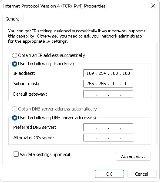
- Access the IPV4 settings of the NIC connecting to the switch and assign a unique static IP address (between 169.254.100.100 and 169.254.100.250) and the subnet to 255.255.0.0.
For example, set as follows and click OK.
IP: 169.254.100.103
Subnet: 255.255.0.0
Default Gateway: 0.0.0.0
- Download NETGEAR Engage Controller application from NETGEAR’s website
- Install and Run NETGEAR Engage Controller.
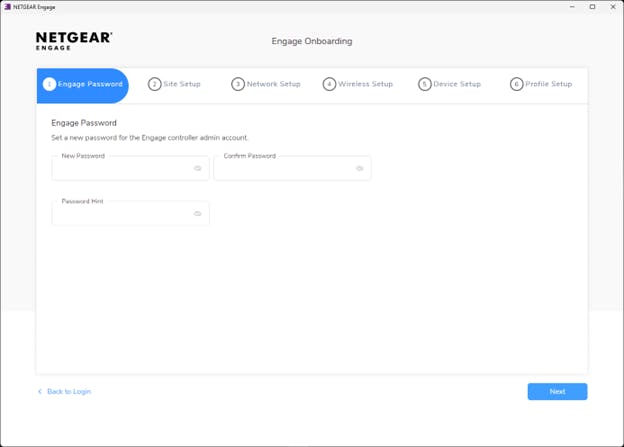
- In Engage Password, set a new password for your Engage controller admin account, and click Next.
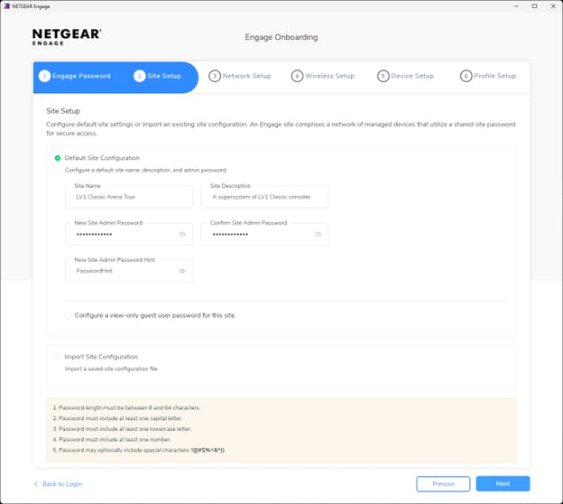
- In Site Setup, create a new Site Name and a password (you can use the same password you used for your admin account), and click Next.
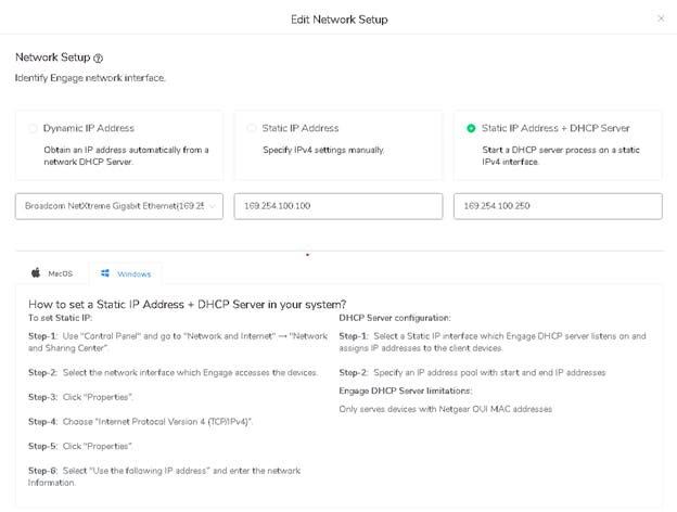
- In Network Setup:
- At the top, choose ' Static IP Address + DHCP server’.
This will allow Engage app to use a temporary DHCP server which will automatically assign a unique IP address to each switch in the network. - In the Engage Network Interface (at the left), choose the relevant NIC you use to connect to the switch.
- In the IP ranges field, make sure you see a range of IP Addresses from 169.254.100.100 – 169.254.100.250
- Click Next.
- At the top, choose ' Static IP Address + DHCP server’.
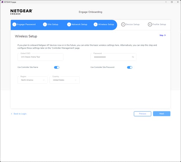
- In Wireless Setup, at the top right, click Skip. In the dialog window click Yes.
- In the Device Setup window:
- Power on the Stage switch (the switch your computer is connected to).
Wait until you see the switch listed in the 'Discovered Devices' section. This may take a minute or two. - Power on the FOH switch.
Wait until you see it in the 'Discovered Devices' section. This may take a minute or two.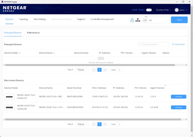
- Power on the Stage switch (the switch your computer is connected to).
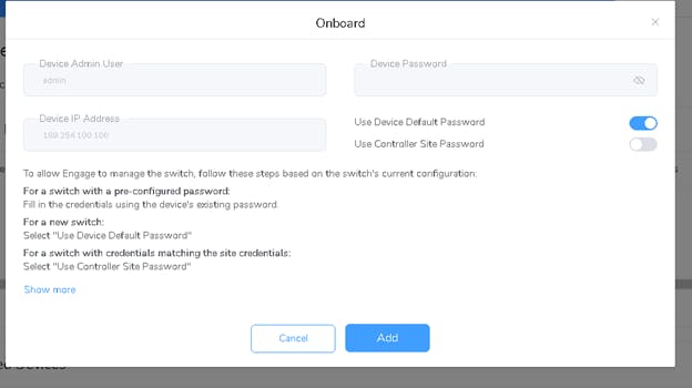
- Onboard the Stage switch:
- In the Discovered Devices section, next to the Stage switch click Onboard.
- Click Continue.
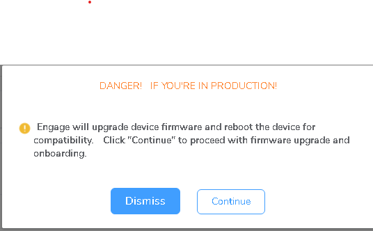 Note: Be aware that the unit might begin a firmware update process. It's crucial to allocate sufficient time for this; avoid performing it in time-critical scenarios.
 - In the Onboard window choose 'Use device default password'.

- Click 'Single' to continue.
- Onboard the FOH switch:
- In the Discovered Devices section, next to the Stage switch click Onboard.
- Click Continue.
Note: Be aware that the unit might begin a firmware update process. It's crucial to allocate sufficient time for this; avoid performing it in time-critical scenarios.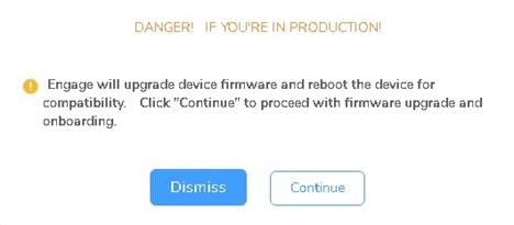
- In the Onboard window choose 'Use device default password'.
- Click 'Single' to continue.
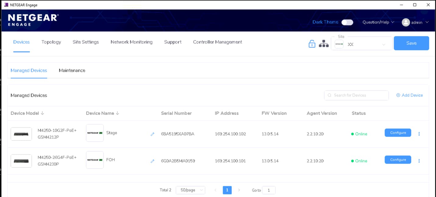
At this point, both network switches will receive a temporary IP address provided by the DHCP server, and both switches will show up under the ‘Managed Devices’section.
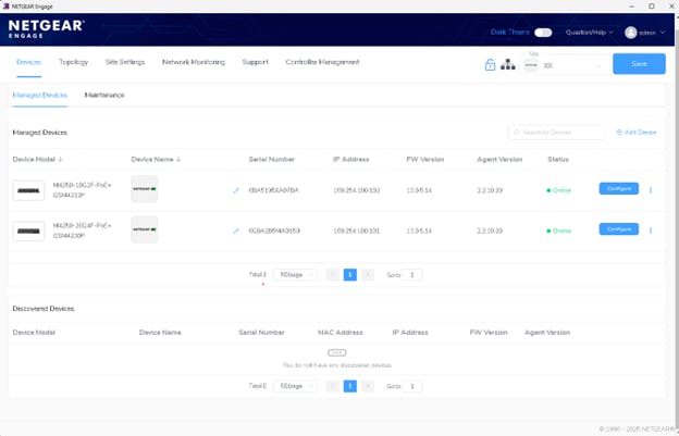
Tip: Set a friendly name to each switch by going to the Managed Devices section and click the pencil icon (located under the Device Name column).
Setting up and configuring both network switches
Set a unique static IP for each switch. This static IP will be the new permanent address to access the switches management interface.
- In the Managed Devices section, in the Stage switch row, click Configure.

- Under Device Details > Management IP Address, click the pencil icon.
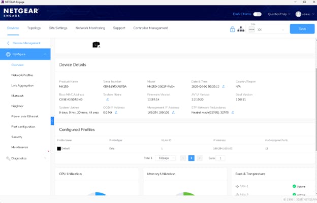
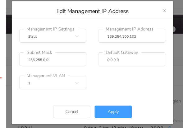
- In the Edit Management IP Settings, select Static.
- Under Management IP Address, enter have a valid address such as 169.254.100.102.
- Subnet Mask should be 255.255.0.0
- Default gateway should be 0.0.0.0
- Under Device Details > Management IP Address, click the pencil icon.
- Click Apply.
 Please note: Remember this IP address. It will be used to access the switch Management interface from now on.
Repeat the same process for your FOH switch, but make sure to give it its own unique Static IP address, such as 169.254.100.101
Setting up the SoundGrid Profile template
On the Stage switch, set the SoundGrid profile for all ports you want to assign to the SoundGrid VLAN. It is recommended to use VLAN 1 as the SoundGrid VLAN, ensuring both SoundGrid traffic and switch management remain accessible.
If you plan to use non-SoundGrid devices or protocols, create a separate dedicated VLAN.
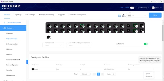
- In the left panel, click on 'Network Profiles'.
- Under Configured Profiles - in the 'Default' row, click on the 3 dots (at the right), and select 'Edit'.
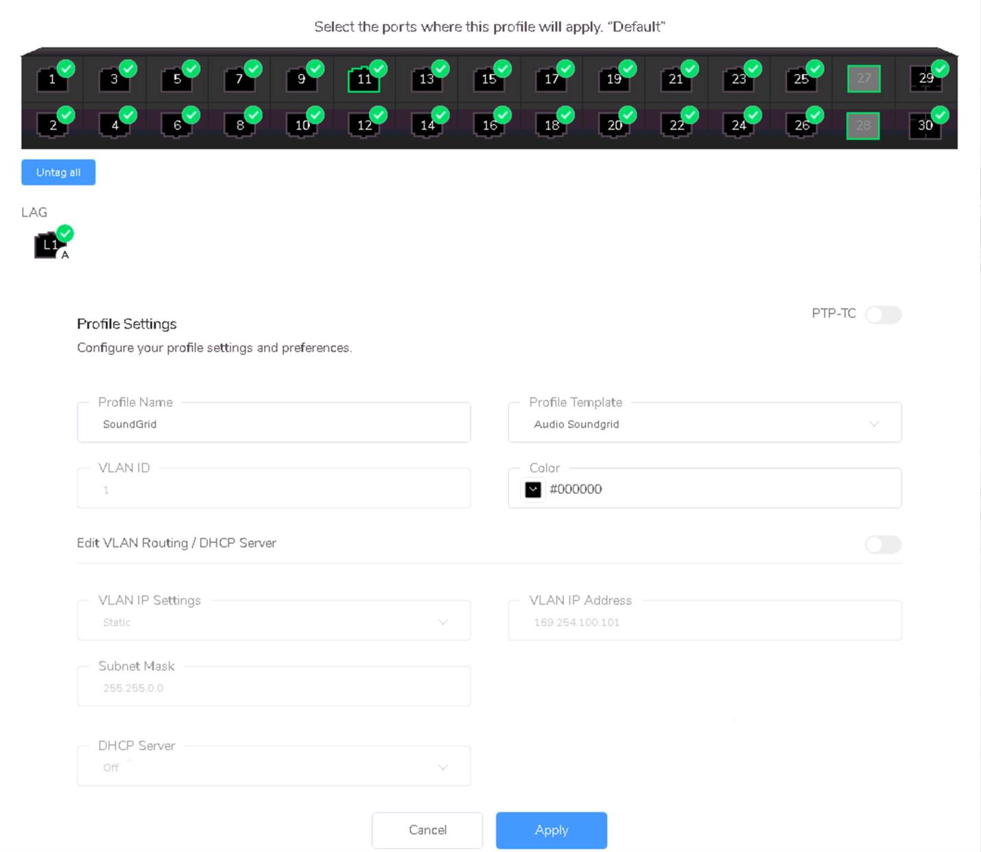
- Select all the ports you want to assign to the SoundGrid VLAN.
- Under Profile template, look for Audio SoundGrid and select it.
- Under Profile Name, type SoundGrid Profile.
- Click Apply.
Verify LAG has been established
To verify that a LAG has been created properly, follow these steps:
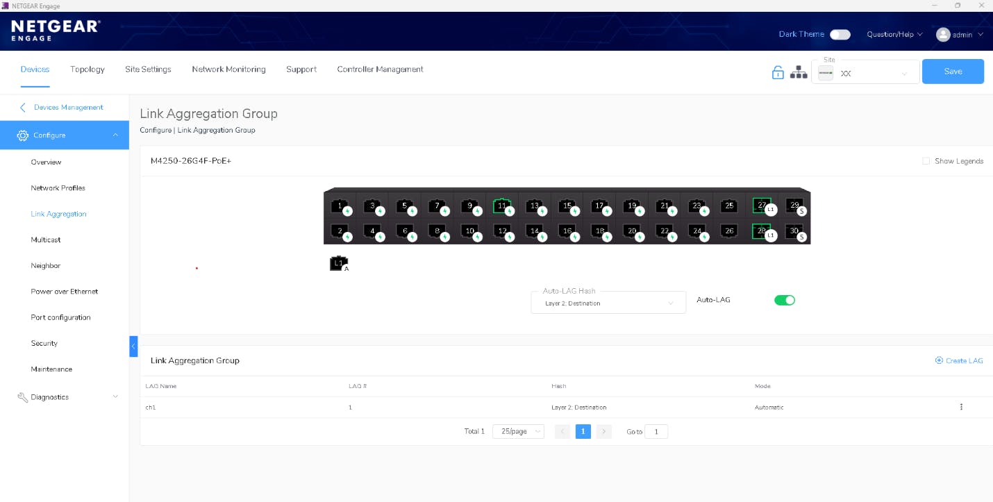
- In the left panel click on Link Aggregation, and verify that the ports you use to connect the switches to each other are marked as 'L1'.
In the example below we see ports 27 and 28 marked as ‘L1;, indicating that they are part of LAG 1. - Set 'Mode' as 'Automatic' listed (Should be set by default).
- Set Auto-Hash LAG to 'Layer 2: Destination' (Should be set by default).
- Enable ‘Auto-Lag’ (Should be set by default).
Repeat the same process for the FOH switch.
Once you have finished configuring both switches, click SAVE at the top right of the NETGEAR Engage app.
Both switches are now properly configured and ready to be used.
Important notes
- Using etherCON Panel Connectors:
Use high-quality components from reputable brands.
It's important to match cable types with the etherCON connector you use. Mismatching categories can result in poor mating, unstable connections, and degraded performance:- Cat6a or Cat5e cable connectors are compatible with either Cat6a or Cat5e panel connectors.
- Cat6a and Cat5e cable connectors are not compatible with Cat6 panel connectors.
- Cat6 cable connectors are not compatible with Cat5e or Cat6a panel connectors.
- For more information on LAG, relevant cable specifications and compatible SFP connectors, refer to your switch manufacturer’s website, or consult NETGEAR ProAV Design support team.
Useful Resources
- Network Switches and Cables for SoundGrid Systems page
- System Design Guidelines
- Waves Live – Common Questions Answered
- How to Use SoundGrid Network in a VLAN
Need any assistance? Contact our Technical Support team.